Charlie Webber's RF4D
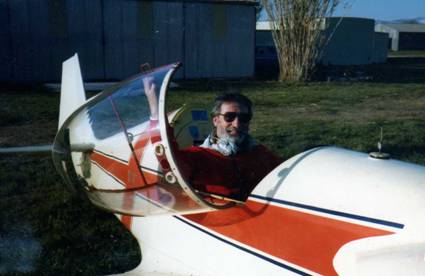
My RF-4. N7723
N7723 is the most modified RF-4 in the world, all without any FAA involvement. We mutually ignored each other. Aerodynamically the RF-4 is as friendly as it looks. Only mechanical changes were needed. A continuous program of mechanical modifications started that ended when I had a minor medical stroke from working on the radio instrument panel. N7723 still wasn’t a racer or an aerobatic thing.
I considered eliminating its N number and selling whatever it was as “a collection of parts” with no performance claims. A buyer would work properly with the FAA and certify N7723 as an EXPERIMENTAL aircraft possibly with a new N number. Somebody in Iceland offered me a wheelbarrow of their currency for the ship. Somebody in Greece is searching for two wheelbarrows. Wheelbarrows are cheap over here on Ebay. I am collecting gold coins again. N7723 might be bartered for a mere 30 troy oz of gold coins thus eliminating many problems of inflation, money values, sales tax, etc. The following describes what now is for sale. If interested contact charleswebber@sbcglobal.net .
A basic RF-4 motor-glider has a weird personality of strange problems. Any well behaved aerobatic wing will stall before it shatters. The single piece RF-4 wing might not stall until 9 g’s and at high speed! What was the ultimate solution has not been studied conclusively. Fournier stiffened the wing somewhat which made it slightly stronger and surprisingly more friendly. The best solution is to simply warn the pilot that the RF-4 is not aerobatic and not to park the stick suddenly in a corner.
At landing speed the wing will stall suddenly. This requires a high landing approach speed until practically touching the ground. Combined with the original bouncy bungee landing gear this can be embarrassing. Ask any J-3 pilot. Elemer made the nicest series of smooth bounces ever seen. He got down to business when he ran out of fuel.
The landing gear’s problem was that bungee springs provided no shock absorbing. Stretching rubber (bungee) experiences negligible hysteresis. On the other hand compressing rubber provides considerable hysteresis. Therefore the answer was to get rid of the bungees and replace them with rubber pads. Fortunately the RF-4 landing gear lent itself to this and I had a surprisingly friendly landing gear. Regardless, you want to be close to the runway before you stall the wing.
The famous RF-4 owner, Jack Lambie, just played with my no-bungees gear.
Fournier tried a different solution with his RF-6. He removed six feet from the RF-4 wingspan making the wing stall at some higher g before it failed, thus making it immune to almost any aerobatic pilot. I flew the RF-6 but not as an aerobatic test pilot. It lost its RF-4 friendliness, a quality that cannot seem to be engineered. The RF-6 had nothing to offer and wasn’t continued. No other options are being tried as of 3/7/2010.
The wood structure is inherently stealthy to radar. The metal in the system was not significant. Radar stations have asked me if I had my transponder operating, whatever that was. A corner reflector about 10” in diameter in the baggage area was barely helpful. I was too cheap to buy an expensive transponder.
RF-4 in Mac’s original color scheme. I am coaxing the ship to ignore the whistles.
Jack Lambie provided some cheap leftover dacron he had. McRiley and I developed techniques to utilize the fascinating Canadian fabric goop material called Hipec. This Hipec is a metal primer that is the only material I have found that honestly bonds to Dacron and apparently anything else. Stitching, taping, and gluing was not needed. Enamel paint is the final layer. The result shows no fabric weave and looks like fibre-glass. Five gallon wing-tanks, wing lights, and electric wiring were also added. There has been no sign of later flaking and peeling and the pull strength is still high. As long as this combination is kept hangared it should last at least another 25 years.
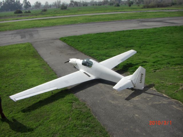
The main purpose of the present plain color scheme, white on top and black on bottom, is to make it as visible as possible in flight. White is least stealthy against a dark earth, and black is least stealthy against a white sky. Like any aircraft it is still invisible head on. It proved to be artistic in itself. Even the N number is taped on.
I couldn’t resist some slight decoration underneath
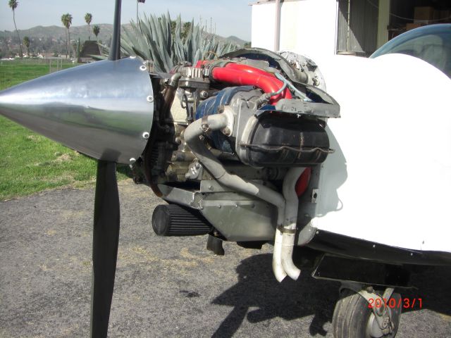
The present 2100 cc Revmaster engine is more than enough. It can climb ~1200 fpm and cruise past 120 mph which now feels unfriendly.
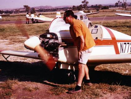
The original RF-4 engine, French Rectimo type 4AR 1200 (1200 cc VW), was insufficient for my weight and the California heat and altitudes. Yet normal flying had remarkable net friendliness. An increase to 1850 cc merely required 92 mm jugs. This power increase was ample. The next increase to a Revmaster 2100 cc involved more stroke and required more volume. The result could cruise above 110 mph but it then felt stiff and unfriendly. The excess power was friendly in climb when needed. The wing tanks fed into the top of the main tank using automotive pumps. The fuel system’s ambient air isolation region at the bottom prevents any possibility of vapor lock because of high temperature cooling air. The slide valve carburetor is immune to ice formation on a rear butterfly valve since it lacks one.
Engine cooling is another area. The cooling air outlet merely needed a small flap to make a major improvement. The lack of such a flap made crossing the Atlantic and then the U.S. really miserable for Slovak. I improved the jug cooling air details which then cooked the fuel system causing the fuel to vapor-lock in the carburetor at 132 degrees F. The cowling made it possible to completely separate the fuel system from this hot engine cooling air.
Finally is the matter of cooling the engine oil. The hot air coming from the jugs does a lousy job. Joe Horvath explained that being automotive, this engine was cooled mainly on its lower crank-case by air coming from the street. In aircraft the crankcase was being cooled by the hot air coming from the jugs. Burt Rutan pointed out the obvious aviation solution (to him since he had no experience) would merely invert the direction of the cooling air the way it is done in a car. This brilliant but tricky solution applies to any aircraft engine.
I thought about the details. It should solve all cooling problems and empty the engine compartment of now surplus fixes. While it is at it, it could kill me with a major medical stroke. So it is being left for the next owner.
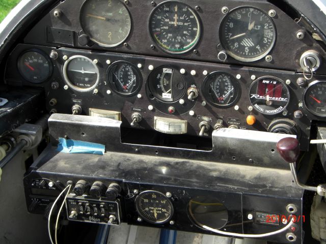
This shows the three-section plug-in instrument panel. The lower radio section is not quite completed. The fuel primer pump is to the left of it.
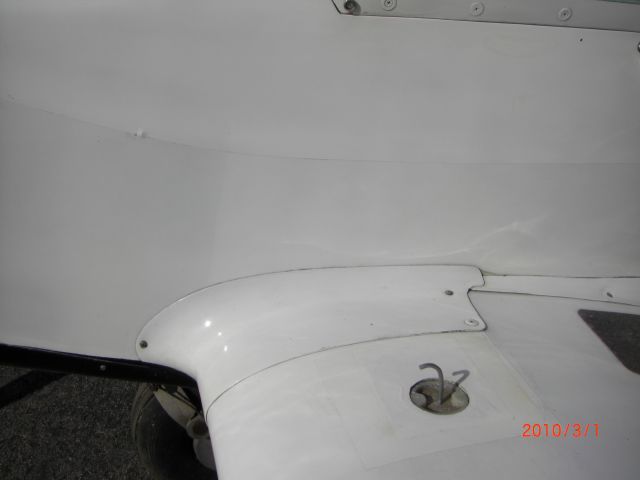
This shows the fuel entry for the 5 gal. left wing tank. The ram air pressure horn is in place.
This shows the main tank fuel cover with gauge (showing empty). The ram pressure hole on the ferrule must point forward or it sucks on the fuel tank.
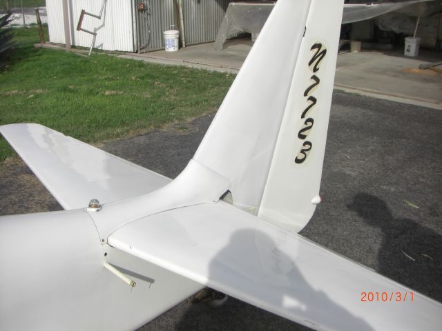
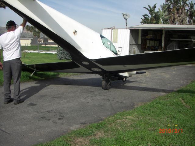
This is the tail section showing lift handle extended. The N number is taped on. Tail lights are in place but not hooked up. With tail wheel free-wheeling you can back up without lifting tail.
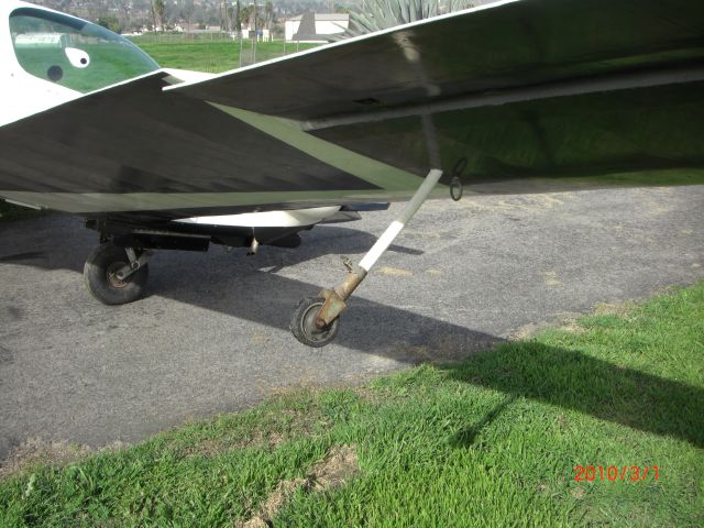
Right plastic outrigger with large wheel. Tie-down ring (removable) seen.
The original steel outriggers were complex and performed poorly. Larger wheels and plastic material provided a substantial improvement. Jack Lambie was amazed. He experimented with winglet tips containing small wheels. They were lower drag in the air but awful on the ground.
The tail wheel allows taxi control against a 45 mph cross wind before disengaging into a free-wheeling condition. One person can push at the prop for ground handling.